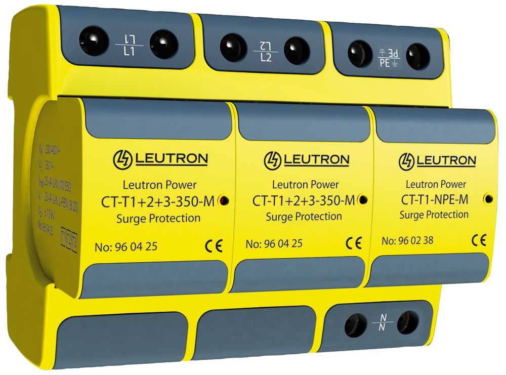
CT-T1+2+3/2+1-350-FM
Article Nr. : 960413
They provide extremely high discharge capacity with at the same time very low protection levels and they also do not need any damageable internal or external electronic trigger. Combined arrester with rare-gas-filled spark gap and very low protection level < 1.0 kV.
- Combined Arresters Class I+II+III (T1+T2+T3)
- Test standard: IEC 61643-11 / EN 61643-11
- Vibration test standard: DIN EN 60068-2-6, IEC 60068-2-6
- Shock test standard: DIN EN 60068-2-27, IEC 60068-2-27
- Mounting on 35 mm DIN rail (EN 60715)
- Enclosure material: thermoplastic with the colours yellow and black
- No leakage currents, thus, allowing installation upstream of power meters
- Optical status indication (red pin appears)
- Single modules can be replaced easily
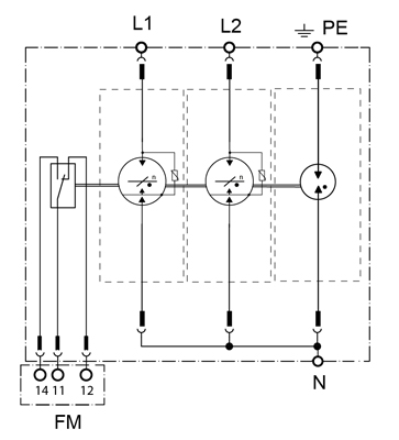
- Remote changeover contact (FM)
- EAC certification
| IEC category | Type 1 + 2 + 3 / class I+II+III |
| Nominal voltage ACUN | 230/400 V~ |
| Max. continuous operating voltage AC (50/60 Hz) Uc | 350 V~ |
| Lightning impulse current (10/350 µs) totalItotal | 100 kA |
| Lightning impulse current (10/350 µs) L-N/N-PE/L-PENIimp | 25 / 100 / - kA |
| Nominal discharge current (8/20 µs) L-N/N-PE/L-PENIn | 25 / 100 / - kA |
| Protection levelUp | ≤ 1,0 kV |
| Follow-on current extinguishing capability AC L-N (260 V AC) Ifi | 4 kAeff |
| Follow-on current extinguishing capability AC N-PEIfi | 100 Aeff |
| Short-circuit withstand capability at max. back-up fuseISCCR | 50 kAeff |
Additional Information
| Max. acceptable backup fuse (branch wiring) | 250 A gG |
| Max. acceptable backup fuse (V-type through wiring) | 125 A gG |
| Operating temperature rangeTU | -40 - +80 °C |
| Min. conductor cross section at terminals | 10 mm² solid/flexible |
| Max. conductor cross section | 50 mm² stranded/35 mm² flexible |
| Recommended conductor cross section | 25 mm² |
| Max. connection torque for terminals | 4,0 Nm |
| Power supply system | 2 phase TT system |
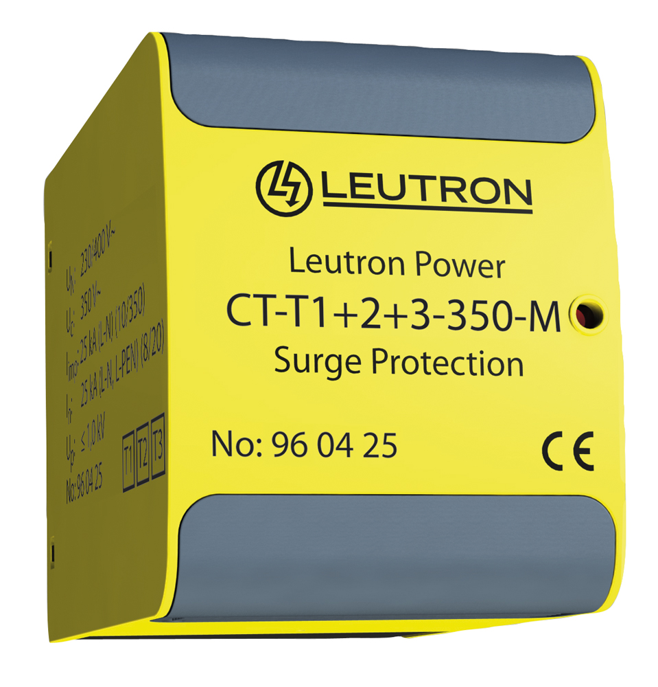
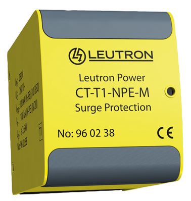
| Composed of: number of moduls | 2x 96 04 25 + 1x 96 02 38 |
| Degree of protection (IEC EN 60529) | IP 20 |
| Inflammability class according to UL 94 | V0 |
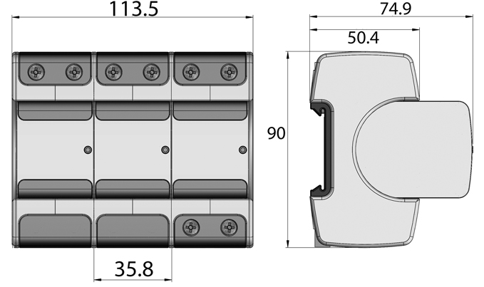
| Installation width | 113,5 mm |
| Max. operating current remote contact FM | 1 A AC/200 mA DC |
| Max. operating voltage remote contact FM | 250 V AC/125 V DC |
| Max. conductor cross section FM | 1,5 mm² |
| Max. locking torque FM terminals | 0,25 Nm |
| Mounting on | 35 mm DIN rail (EN 60715) |


