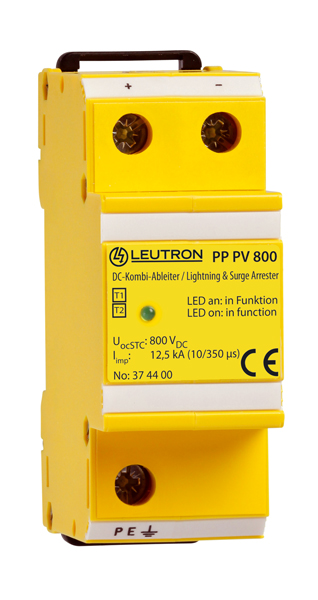
When applied in PV installations, these devices are placed inside the connection box of the solar generator and on the DC side of the inverter.
- Remote signalling contact: break contact
- DC Combined Arrester Type 1+2
- Two-pole combined lightning current and surge arrester dc, type 1 + type 2
- Applicable at the LPZ transition point 0A-1 and higher
- Test standard: IEC 61643-11 / EN 61643-11
- Mounting on 35 mm DIN rail (EN 60715)
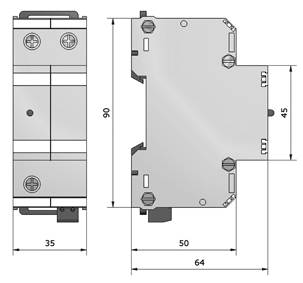
- Space required for installation: 36 mm
- EAC certification
| IEC category | Type 1 + 2 / class I+II |
| PV voltageUocSTC | 800 V= |
| Max. continuous operating voltage DCUc | 850 V= |
| Protection level at In (8/20 µs)Up | ≤ 2,2 kV |
| Protection level at 5 kAUp | ≤ 1,8 kV |
| Response timetA | ≤ 25 ns |
| Lightning impulse current (10/350 µs) per poleIimp | 12,5 kA |
| Max. impulse discharge current (8/20 µs)Imax | 40 kA |
| Operating temperature rangeTU | -40 - +80 °C |
| Min. conductor cross section at terminals | 10 mm² |
Additional Information
| Max. conductor cross section | 35 mm² stranded/25 mm² flexible |
| Max. connection torque for terminals | 4,0 Nm |
| Enclosure material / colour | polycarbonate (halogen-free) UL 94-V0 / yellow |
| Degree of protection (IEC EN 60529) | IP 20 |
| Dimension (DIN 43880) | 2 TE |
| Mounting on | 35 mm DIN rail (EN 60715) |
| FM contact / contact type | break contact |
| Switching capacity FM | 250 V/2 A |
| Max. conductor cross section FM | 1,5 mm² |
| Max. locking torque FM terminals | 0,25 Nm |
| Recommended conductor cross section | 25 mm² |


